
For many milled components, adding more machine axes does not automatically produce a better part. The right process is the one that reaches every required feature, maintains the specified tolerances, and avoids unnecessary setup or programming costs. For brackets, plates, housings, panels, fixtures, and many other components, 3 axis cnc machining remains a practical and economical choice.
This guide explains how 3 axis cnc machining works, which parts it can produce, where its limits appear, and what engineers should consider before requesting a quotation. It also covers materials, tolerances, surface finishes, quality control, cost drivers, and the differences between three-axis and multi-axis milling.
What Is 3 Axis CNC Machining?
3 axis cnc machining is a subtractive manufacturing process in which a computer-controlled cutting tool moves along three linear axes. The X axis moves from left to right, the Y axis moves from front to back, and the Z axis moves vertically. By coordinating these movements, the machine removes material from a solid workpiece until the programmed geometry is formed.
On a typical vertical machining center, the workpiece is clamped to the machine table while the cutting tool rotates in the spindle. During 3 axis cnc machining, the machine can move along X, Y, and Z at the same time, but the workpiece does not automatically rotate toward the tool. Features on another side usually require the operator to stop the machine, reposition the part, and establish a new work coordinate.
In 3 axis cnc machining, the process is sometimes called three-axis milling or 3-axis CNC milling. These terms describe the same basic relationship between the tool and the workpiece, although machine configuration, control software, spindle performance, and tooling may differ from one shop to another.
How the Three Axes Work
The three controlled directions define what the cutting tool can reach in a single setup. X and Y position the tool across the working plane, while Z controls cutting depth. In 3 axis cnc machining, these movements can create flat faces, stepped levels, slots, pockets, hole patterns, angled surfaces, and many contoured features.
Consider a rectangular aluminum enclosure. The machine can face the top surface, mill the outside profile, open an internal pocket, drill mounting holes, and tap threads from above. If the enclosure also needs holes on its side walls, 3 axis cnc machining can still make them, but the part normally needs another setup so that each side faces the spindle.
This setup logic matters in 3 axis cnc machining. A part may be technically possible on a three-axis mill yet inefficient if it requires repeated repositioning, difficult alignment, or several custom fixtures. Process selection should therefore consider access and setup count, not just the overall shape shown in the CAD model.
The Typical 3 Axis CNC Machining Workflow
A stable result begins before material reaches the machine. A professional 3 axis cnc machining project normally follows a controlled sequence from drawing review to final inspection. Keeping this sequence consistent helps 3 axis cnc machining remain repeatable across prototype and production orders.
1. CAD File and Drawing Review
The engineering team first reviews the 3D model and 2D drawing. The model defines geometry, while the drawing identifies critical dimensions, tolerances, threads, surface roughness, datum systems, and finishing requirements. This review determines whether 3 axis cnc machining provides adequate tool access and whether the design needs special fixtures or additional setups.
2. Design for Manufacturability Analysis
DFM analysis checks internal corner radii, pocket depth, wall thickness, hole depth, tool reach, workholding surfaces, and tolerance requirements. A small design adjustment can often allow shorter tools, simpler fixtures, and more stable cutting. That makes 3 axis cnc machining faster without changing the part's intended function.
3. Material Preparation and Workholding
Raw stock is cut to a suitable size and secured with a vise, clamps, soft jaws, fixture plate, or a custom fixture. Reliable workholding prevents movement while avoiding distortion. This is especially important when 3 axis cnc machining is used for thin walls, plastics, or soft metals that can deform under excessive clamping force.
4. CAM Programming and Toolpath Planning
CAM software converts the part geometry into toolpaths for 3 axis cnc machining. The programmer selects cutting tools, spindle speeds, feed rates, stepovers, depths of cut, entry methods, and machining order. Good programming keeps the tool engaged efficiently and reduces vibration, heat, unnecessary air cutting, and abrupt changes in load.
5. Roughing and Finishing
Roughing removes most of the excess stock as efficiently as possible. Semi-finishing may leave a controlled allowance, and finishing passes bring critical surfaces to their final dimensions and texture. In 3 axis cnc machining, separate tools are often used for facing, pocketing, profiling, drilling, reaming, chamfering, and thread production.
6. Repositioning When Required
If features cannot be reached from the first orientation, the operator turns or relocates the workpiece. Accurate datums, probing, locating pins, and purpose-built fixtures help preserve the relationship between features. Every new setup in 3 axis cnc machining introduces time and another opportunity for alignment variation, so setup reduction is an important part of process planning.
7. Inspection and Post-Processing
Dimensions are checked during and after 3 axis cnc machining with suitable measuring equipment. The part may then receive deburring, anodizing, plating, passivation, polishing, sandblasting, painting, black oxide, laser marking, or another specified finish. Final inspection confirms that machining and post-processing results meet the drawing.
Common Operations
The versatility of 3 axis cnc machining comes from the number of operations that can be completed on one platform. Common processes include:
Facing to create a flat reference surface
Profiling around the outside of a component
Pocketing to remove material from enclosed areas
Slotting and keyway cutting
Drilling, counterboring, and countersinking
Boring and reaming for controlled hole size
Tapping and thread milling
Chamfering and edge breaking
Engraving and simple three-dimensional contouring
These operations allow 3 axis cnc machining to produce both functional prototypes and production parts. The actual 3 axis cnc machining operation sequence depends on geometry, material, tolerance, available tool length, and whether all features can be reached from practical workpiece orientations.
Parts Well Suited to 3 Axis CNC Machining
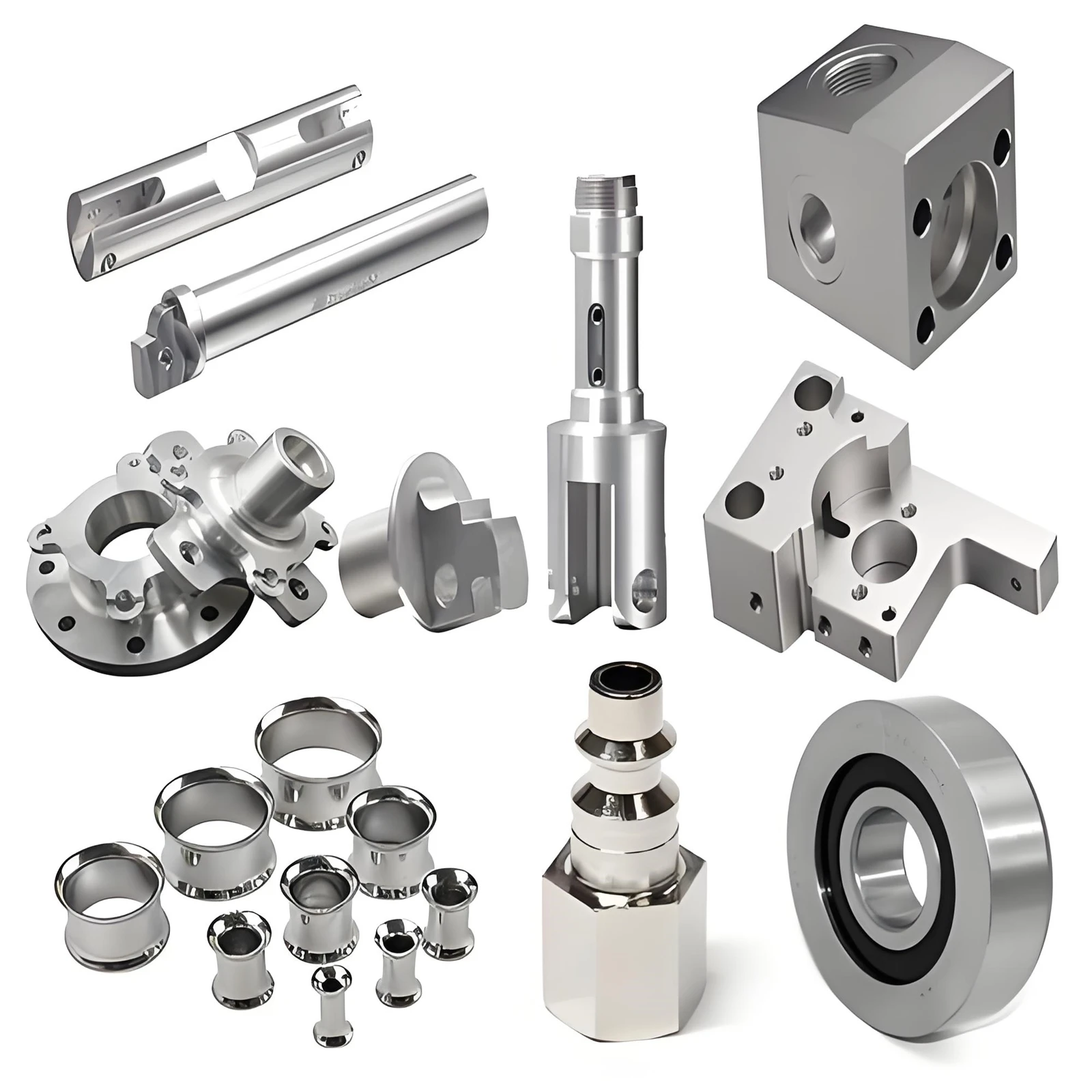
The process works best when most important features can be approached from one direction or from a small number of straightforward orientations. Typical 3 axis cnc machining parts include equipment plates, machine brackets, electronic housings, heat sinks, manifolds, jigs, fixtures, mold inserts, covers, mounting bases, and instrument panels.
It is also effective for components with 2.5D geometry. In this context, 2.5D means that the part contains multiple depths and profiles but does not require the cutting tool to approach severe undercuts or continuously changing compound angles. Many industrial components fall into this category even when their drawings look detailed.
Some free-form surfaces are also possible. A ball-end mill can follow closely spaced toolpaths across a contoured area, allowing 3 axis cnc machining to produce molds, product surfaces, and gradual curves. Surface quality and cycle time depend on tool diameter, stepover, machine rigidity, and the shape's accessibility.
Materials That Can Be Machined
Material behavior directly affects tool selection, cutting speed, heat, chip control, achievable finish, and cost. Youde machines a broad selection of metals and engineering plastics, allowing 3 axis cnc machining to support prototypes as well as end-use parts.
Metals
Aluminum is widely used because it combines low weight, corrosion resistance, and good machinability. Common applications include housings, brackets, heat sinks, robotics components, and automotive prototypes. Steel and stainless steel provide greater strength or corrosion resistance but normally require lower cutting speeds and more attention to tool wear.
Copper and brass are used for conductive parts, fittings, electrical components, and decorative features. Titanium offers a high strength-to-weight ratio and corrosion resistance, although heat control and stable tooling are essential. In each case, 3 axis cnc machining parameters must be matched to the specific grade rather than the broad material name alone.
Engineering Plastics
ABS, PP, PE, PMMA, acrylic, nylon, PC, POM, PPS, PEK, and other machinable plastics are suitable for many prototypes, insulators, covers, gears, guides, and medical or electronic components. Plastic 3 axis cnc machining requires careful control of heat and clamping. Excessive heat can soften the material, while excessive fixture pressure can distort it before measurement.
Material selection for 3 axis cnc machining should start with the component's operating conditions. Strength, stiffness, weight, temperature, chemical exposure, electrical behavior, wear, appearance, and budget all matter. Machinability is important, but it should not replace functional requirements.
Main Advantages
The first advantage of 3 axis cnc machining is efficiency. Three-axis equipment is widely available, programming is relatively direct, and common cutters and workholding systems can handle a large range of parts. When geometry matches the process, this combination can shorten preparation time and control per-part cost.
The second advantage of 3 axis cnc machining is flexibility. No dedicated production mold is required, so a CAD file or drawing can be revised between batches. This makes 3 axis cnc machining useful for one-off components, product development, replacement parts, bridge production, and low-volume manufacturing.
Repeatability is another important benefit of 3 axis cnc machining. Once the program, tools, work offsets, and inspection plan are established, the same process can reproduce the component across a batch. Repeatability still depends on material consistency, tool condition, temperature, fixture stability, and process control; CNC control does not remove the need for inspection.
Finally, the process can combine several operations in one setup. A top face may be milled, pocketed, drilled, reamed, tapped, and chamfered before the part leaves the fixture. Well-planned 3 axis cnc machining reduces handling and helps maintain dimensional relationships between features made from the same orientation.
Limitations and Geometry Challenges
The central limitation is tool access. Because the workpiece does not automatically tilt or rotate, 3 axis cnc machining cannot directly reach every side, undercut, or compound angle from a single setup. Deep cavities may also require long tools, which are more likely to deflect or vibrate.
Perfectly sharp internal corners are not possible with a rotating round cutter. Designers should include an internal radius large enough for a practical end mill. Deep narrow pockets, very thin walls, and extreme depth-to-diameter holes can slow 3 axis cnc machining and make dimensional control more difficult.
Multiple orientations can extend the range of 3 axis cnc machining, but they add fixture work, operator time, and alignment risk. If a component needs machining on five sides, numerous angled holes, or continuous sculptured surfaces, a 4-axis or 5-axis strategy may reduce setups and produce a more stable result.
3 Axis vs. 4 Axis vs. 5 Axis Machining
In 3 axis cnc machining, all controlled motion is linear. Four-axis equipment adds a rotary axis, allowing the workpiece to rotate for features around a cylindrical or multi-sided component. Indexed four-axis machining positions the workpiece at a set angle before cutting, while simultaneous four-axis machining can move the rotary and linear axes together.
Five-axis machining adds another rotational degree of freedom. It is well suited to impellers, aerospace structures, medical components, deep cavities, compound angles, and parts that benefit from reaching several faces in one clamping. It can also use shorter tools by tilting the workpiece or spindle toward a feature.
More axes, however, bring more complex programming, process planning, and equipment costs. If 3 axis cnc machining can complete a part in one or two stable setups, moving it to a five-axis center may offer little practical benefit. Comparing 3 axis cnc machining with multi-axis options should be based on feature access, tolerance relationships, setup count, surface requirements, quantity, and total manufacturing cost.
Tolerances and Surface Finish
Machine axis count does not determine accuracy on its own. The result of 3 axis cnc machining depends on machine condition, spindle runout, fixture rigidity, tool deflection, thermal stability, material stress, programming, operator control, and inspection methods.
For 3 axis cnc machining, Youde's standard CNC milling tolerance is listed as ±0.05 mm, while tighter requirements may be evaluated for suitable parts. A tolerance should always be assigned according to function. Applying an unusually tight limit to every dimension increases machining and inspection effort without necessarily improving assembly performance.
Surface finish is affected by cutter geometry, feed per tooth, spindle speed, stepover, tool wear, material, and vibration. A visible machined surface may be acceptable as cut, while sealing faces, bearing locations, or cosmetic areas may need a defined roughness or secondary treatment. For 3 axis cnc machining, the drawing should distinguish critical surfaces from general ones.
Design Guidelines for Better Results
Good design makes 3 axis cnc machining more predictable. Use generous internal corner radii so the shop can select a rigid cutter. Avoid making pockets substantially deeper than necessary, and provide tool access around walls and bosses. A deep cavity with small corner radii may force the use of a long, slender end mill even when most of the cavity could be cut with a larger tool.
For stable 3 axis cnc machining, keep walls thick enough to resist cutting and clamping forces. If thin walls are functionally necessary, indicate which surfaces and dimensions are critical so the machining sequence can be planned around deformation. Add accessible, stable surfaces for workholding whenever the design permits.
Use standard hole sizes and thread specifications where possible. Blind holes need room for the tool tip and chips, and threads usually should not extend to the absolute bottom of a blind hole. In 3 axis cnc machining, realistic hole depth and thread engagement often save more time than small changes to the external profile.
Apply tight tolerances in 3 axis cnc machining only to mating, sealing, locating, bearing, or otherwise functional features. Define datums clearly and use GD&T where it communicates design intent better than independent plus-or-minus dimensions. If several critical features must align across different faces, discuss setup and inspection strategy before production.
What Determines Cost?
The price of 3 axis cnc machining is shaped by material cost, stock size, programming, tooling, cycle time, setup count, fixture requirements, quantity, tolerances, inspection, and finishing. Physical size alone is a poor cost predictor. A small stainless steel component with deep pockets and several precision holes may take longer than a large, simple aluminum plate.
Setup count deserves special attention. Reorienting a component requires handling, new work offsets, and often another inspection stage. Designing features so they can be reached from fewer directions can lower the cost of 3 axis cnc machining without changing material or overall dimensions.
In 3 axis cnc machining, quantity changes how preparation costs are distributed. A one-piece prototype carries all programming and setup cost in one unit, while a larger batch spreads that work across more parts. At higher quantities, fixture design, tool life, cycle optimization, and repeatable inspection become increasingly important.
Quality Control for Reliable Parts
Quality control should match the drawing and the risk of the application. A typical 3 axis cnc machining inspection plan may include incoming material verification, first-piece inspection, in-process checks, tool monitoring, and final dimensional inspection. Calipers, micrometers, height gauges, pin gauges, surface roughness testers, optical systems, and coordinate measuring machines may be selected according to feature type and tolerance.
The inspection method for 3 axis cnc machining must be capable of resolving the required tolerance. It also needs a clear datum strategy so the part is measured in a way that reflects its function. For repeat orders, inspection records and stable process documentation help maintain consistency from one batch to the next.
Surface Finishing Options
Machined parts may be used directly after deburring or may receive a secondary finish. Youde supports finishing options that include anodizing, chrome or nickel plating, copper plating, passivation, spray painting, sandblasting, polishing, black oxide, silkscreen printing, and laser marking.
The finish for a 3 axis cnc machining part should be selected early because it can affect dimensions, masking, edge condition, surface appearance, and corrosion performance. For example, a coating can change the final size of a close-fitting feature. When 3 axis cnc machining produces parts that will be anodized or plated, the machining and finishing requirements should be evaluated together.
Applications Across Industries
3 axis cnc machining supports automotive parts, electronic products, consumer products, medical devices, lighting components, communications equipment, robotics, machinery, new-energy systems, and aerospace development. The same basic process can serve very different applications because the program, material, tools, tolerances, and inspection plan are customized for each drawing.
For prototyping, the main value of 3 axis cnc machining is speed and the ability to test a component in production-intent material. For low-volume manufacturing, 3 axis cnc machining avoids the tooling investment associated with molding or casting. For established products, it can provide repeatable production of brackets, housings, fixtures, replacement parts, and other machined components.
Youde's 3 Axis CNC Machining Capabilities
Youde has provided CNC machining services since 2005 and supports projects from prototypes through low-volume production. Our vertical machining centers perform 3 axis cnc machining, while indexed 4-axis and 5-axis resources are available when part geometry requires a different approach. This equipment range allows the process to be selected around the component rather than forcing every drawing onto one machine type.
Our CNC milling operations include boring, counterboring, countersinking, drilling, pocketing, profiling, reaming, and tapping. Available materials include aluminum, steel, stainless steel, copper, brass, and a broad range of engineering plastics. For 3 axis cnc machining, the standard listed milling tolerance is ±0.05 mm, subject to material, geometry, feature size, and drawing review.
The published capacity for 3 axis cnc machining reaches 1200 × 1000 × 400 mm, with customized requirements reviewed separately. Surface treatments and secondary operations can be coordinated after machining. We support prototype and low-volume orders, and standard CNC milling lead time is generally listed at 5–8 working days; actual timing depends on part complexity, quantity, material availability, inspection, and finishing.
Information to Include in an RFQ
An accurate 3 axis cnc machining quotation needs more than a screenshot or overall dimensions. Send a 3D CAD file together with a 2D drawing whenever tolerances, threads, fits, or finish requirements matter. STEP and IGES files are widely used for geometry, while PDF or DWG drawings can communicate controlled dimensions and notes.
The 3 axis cnc machining RFQ should identify material and grade, quantity, critical tolerances, surface roughness, threads, required finish, inspection documentation, and target delivery date. If a material substitute or design adjustment is acceptable, state that as well. Complete information allows the engineering team to review manufacturability and avoid assumptions that could affect price or function.
Frequently Asked Questions
Is 3 axis cnc machining accurate enough for precision parts?
Yes. 3 axis cnc machining can produce accurate parts when the machine, tooling, fixtures, program, material, and inspection method are suited to the requirement. Accuracy should be evaluated feature by feature. The number of axes does not by itself define the tolerance a machine can hold.
Can 3 axis cnc machining produce complex shapes?
3 axis cnc machining can produce pockets, contours, hole patterns, stepped surfaces, and many free-form features. Complexity becomes a problem when the cutter cannot reach a feature, when an undercut is required, or when repeated orientations make alignment inefficient.
Does every side require a separate setup?
Not always. Several features on the same accessible face can be completed together. Features on an opposite or side face generally require the part to be repositioned unless rotary-axis equipment or angle tooling is used.
Is 3 axis cnc machining suitable for prototypes?
Yes. It requires no dedicated mold and can machine production-grade metals or plastics directly from digital files. Design changes can also be introduced without replacing expensive hard tooling.
When should a part move to 5-axis machining?
Consider five-axis equipment when the part contains compound angles, deep difficult-to-reach features, extensive machining on several faces, or critical relationships that would be hard to maintain across repeated setups. A DFM review can compare the total process rather than machine hourly rates alone.
What is the best way to reduce machining cost?
Reduce unnecessary setup changes, avoid excessively deep pockets, use practical corner radii, specify standard holes and threads, and reserve tight tolerances for functional features. Increasing the order quantity may reduce the setup cost per part, but geometry and machining time remain important.
Choosing the Right Process
3 axis cnc machining continues to be one of the most useful milling methods because it balances capability, availability, flexibility, and cost. It can produce a wide range of precise metal and plastic parts without dedicated molds, and it adapts well to prototype changes and low-volume orders.
The limits of 3 axis cnc machining are equally important. Tool access, setup count, deep cavities, undercuts, and compound angles can shift the advantage toward four-axis or five-axis equipment. The most reliable decision comes from reviewing the complete drawing, not from assuming that more axes are always better.
If you are preparing a new 3 axis cnc machining project, send Youde your CAD files, engineering drawings, material requirements, quantity, critical tolerances, and finishing specifications. Our team can review the design, confirm the appropriate process, and prepare a quotation based on the actual manufacturing requirements.
Tags: 3 axis cnc machining, 3-axis CNC machining, 3 axis machining, 3-axis milling, CNC milling, custom CNC machining, CNC machined parts, precision CNC machining