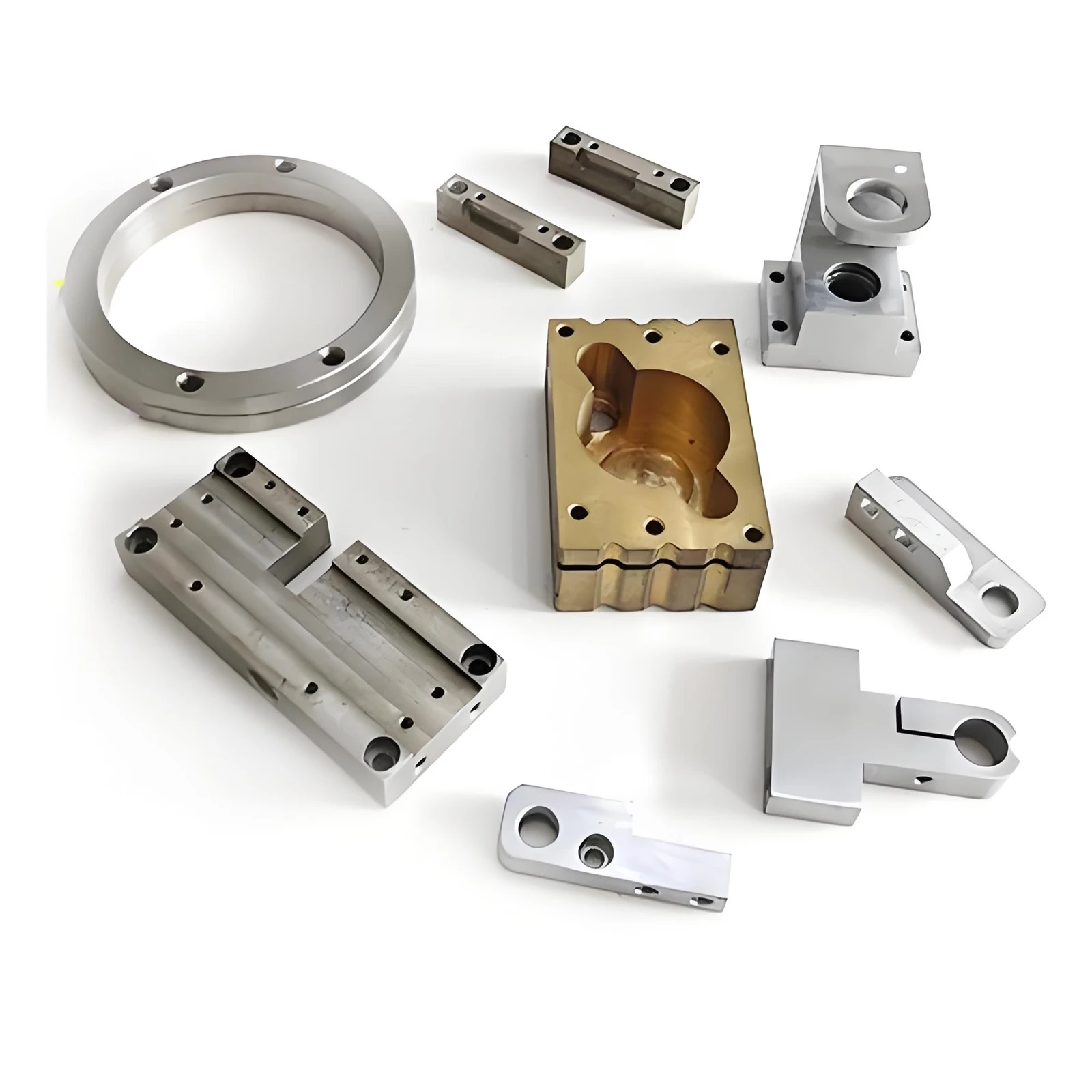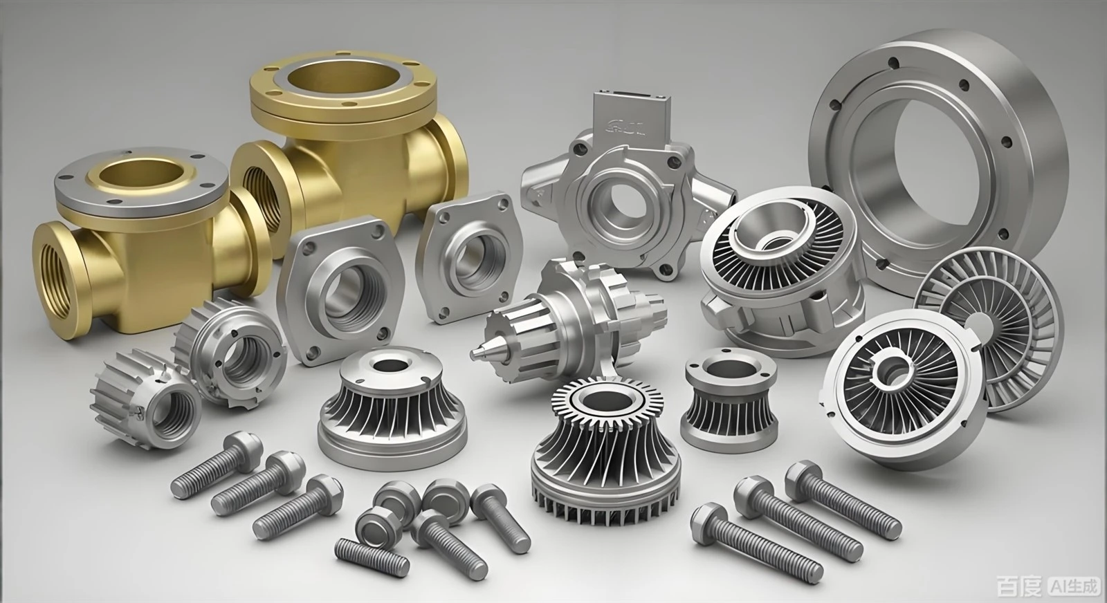

A shipment arrives. Critical dimensions fall outside the print. Surface marks prevent a proper seal. Thin sections have bowed after the clamps were released. Assembly stops, schedules slip, and the buyer must decide between concessions, rework, or a full replacement order. These problems are CNC machining defects, and they remain a frequent source of cost and delay for precision components, including CNC machined car parts.
This article reviews the defects that appear most often in production, the process conditions that create them, and the practical controls that keep them out of finished lots. The emphasis is on steps purchasing and engineering teams can apply when preparing drawings or evaluating suppliers.
The Cost of Defects in Practice

Quality-related costs in manufacturing commonly fall in the 15–20 % of sales range according to American Society for Quality (ASQ) benchmarks; mature operations aim for figures below 5 %. The largest shares usually come from scrap, rework, and the downstream effects of late or non-conforming parts.
In high-mix CNC turning environments, aggregated audit data from Tier-1 automotive and aerospace suppliers has shown average scrap rates in the 3.8–6.2 % range. One documented lean-implementation case on aluminum 7075 disc components recorded a drop from 4.7 % to 1.3 % after setup standardization and SPC-based tool management, without new machine tools. At typical aerospace-grade part values in the mid-double-digit dollar range, even a few percentage points of scrap reduction on a high-volume line can translate into six-figure annual savings.
International supply chains magnify the impact. A dimensional error found only at the customer's assembly plant triggers return logistics, customs delays, and often an entire replacement batch. The true cost therefore extends well beyond the material and spindle time of the defective pieces. The same risks apply when sourcing CNC machined car parts, where tight packaging constraints and sealing requirements leave little margin for error.
Common Defect Types and Their Drivers
The following table organizes the defects that generate the majority of non-conformances in precision CNC work.
|
Defect |
Typical Appearance |
Primary Drivers |
Functional Risk |
|
Dimensional inaccuracy / tolerance drift |
Features outside print limits; size or position changes after unclamping |
Uncompensated tool wear, thermal growth, fixture deflection, residual stress release |
Assembly interference or excessive clearance |
|
Surface finish defects |
Visible tool marks, chatter bands, burrs, Ra above specification |
Incorrect speeds/feeds, worn edges, vibration, poor chip evacuation |
Seal leakage, accelerated wear, fatigue initiation, cosmetic rejection |
|
Warping / distortion |
Bow, twist, or loss of flatness after fixture release |
Uneven stock removal, residual stress in the billet, over-clamping of thin walls |
GD&T failure, inability to assemble or seal |
|
Tool marks & chatter |
Wavy or harmonic patterns on machined surfaces |
Long tool overhang, weak workholding, spindle-speed resonance |
Roughness increase, visual rejection, potential stress concentrations |
|
Copper-specific issues |
Built-up edge, smearing, heat-related size change |
High thermal conductivity and tendency of copper to adhere to the cutting edge |
Surface quality loss, dimensional shift |
|
Stainless-specific issues |
Rapid tool wear, work-hardened layers, heavy burrs |
High hardness and rapid work-hardening rate |
Short tool life, added deburring cost, surface damage |
Dimensional and surface-finish problems account for the largest share of documented rejections in many shops. Warping is especially common on thin-wall aluminum and large plate components. Copper and stainless each require dedicated parameter sets; applying aluminum defaults almost guarantees one of the defects listed above. These material-specific challenges become particularly visible when teams move from aluminum work into copper rapid CNC machining or stainless steel rapid CNC machining, where short lead times leave less room to recover from process drift.
Underlying Process Causes
Most defects trace to a limited set of controllable factors:
Tooling and wear management – edges run past their useful life or geometry mismatched to the alloy.
Workholding – clamping forces that distort thin sections or fixtures that leave critical features unsupported.
CAM and parameter selection – toolpaths that ignore chip load or engagement angle; speeds and feeds copied from a different material.
Material condition – residual stress remaining in the billet or hardness variation between batches.
Incomplete process sheets and inconsistent first-article lock-down allow the same variation to reappear on subsequent lots.
Prevention Measures That Work
Effective control begins before metal is cut and continues through the production run.
At the design stage Submit drawings for a formal DFM review. Request specific feedback on wall thickness, internal corner radii, datum schemes, and tolerance stack-ups. Changes made at this point cost far less than later scrap or rework. This step is especially valuable for CNC machined car parts, where packaging density and sealing surfaces often push geometric limits.
Material preparation Call out stress-relief when residual stress is a known risk. Verify mill certificates and, for critical jobs, sample hardness or microstructure on incoming stock.
Process definition Write material-specific parameter sheets. Copper benefits from polished tools, controlled heat input, and reliable chip clearance-practices that form the foundation of consistent copper rapid CNC machining. Stainless requires rigid setups, speeds that limit work hardening, and effective coolant delivery. Lock the parameters after the first-article run.
In-process control Measure the first pieces thoroughly against the drawing. Apply SPC on critical dimensions during the lot. Replace tools on measured wear or a predetermined limit rather than by visual judgment alone.
Fixture and tool rigidity Keep tool overhang short. Use balanced holders. Design fixtures that support thin sections without excessive clamping force. Separate roughing and finishing tools so surface quality is protected.
A short checklist covering these points, applied consistently, removes the majority of defects that would otherwise reach final inspection.
An Illustrative Improvement Example
Aggregated audit data from Tier-1 suppliers machining aluminum 7075 discs for aerospace applications has shown scrap rates near 4.7 % driven largely by dimensional drift after first-article approval and mid-batch tool wear. After standardizing setup procedures, introducing SPC triggers for tool replacement, and ensuring offline program changes reached the shop floor, one line reduced scrap to 1.3 % within roughly eleven weeks. No new machine tools were required. Similar patterns-documented process sheets, first-article lock-down, and wear-based tool management-appear across other high-mix CNC environments and produce comparable reductions.
Most scrap originates in process variation rather than machine capability. Closing those gaps yields measurable results, whether the parts are aerospace discs or components heading into automotive assemblies.
Evaluating a CNC Machining Partner
When reviewing potential suppliers, focus on concrete evidence:
Does the company return written DFM comments on every new drawing?
Are first-article and in-process measurement records available for review?
How is tool life managed-fixed intervals, measured wear, or operator discretion?
Can they show process sheets for copper or stainless if those materials appear on your parts? Documented experience with copper rapid CNC machining and stainless steel rapid CNC machining is a practical indicator of material-specific process discipline.
For new designs, place a small rapid-prototyping order first. Use the pilot lot to confirm both dimensional stability and surface finish before releasing larger production quantities. A supplier that treats the pilot as process validation rather than a simple price exercise is more likely to maintain consistency when volumes increase.
FAQ
Q: Which defect generates the most rejections?
A: Dimensional inaccuracy and surface-finish shortfalls appear most frequently in rejection data. On thin-wall aluminum housings or large plate brackets, warping often ranks just behind them-especially once the part leaves the fixture and residual stress takes over.
Q: How can tolerance drift be reduced on multi-setup parts?
A: Warm the machine thoroughly before critical cuts, keep coolant temperature stable, and compensate tool wear either in real time or at fixed intervals. Fixtures should locate from the same datums shown on the drawing. Once the first-article results are accepted, lock those exact parameters into the production process sheet so later shifts cannot quietly drift away from them.
Q: Why do copper and stainless steel require different approaches from aluminum?
A: Copper conducts heat rapidly and tends to adhere to the cutting edge, producing built-up edge and smearing. Stainless work-hardens quickly and wears tools faster. Both respond poorly to parameters optimized for aluminum. Shops that treat copper rapid CNC machining or stainless steel rapid CNC machining with the same feeds and speeds used for 6061 almost always see surface and dimensional problems appear within the first few pieces.
Q: What should I request before placing a production order?
A: Ask for a written DFM review, sample inspection reports from similar parts, and a clear description of how first-article results will control the subsequent production run. A small pilot lot remains the most reliable verification step-especially if the part will later become a high-volume CNC machined car part.
Q: How can scrap rate in CNC machining be reduced in practice?
A: Standardize setups, replace tools based on measured wear or SPC triggers rather than operator judgment, stress-relieve stock when residual stress is a known risk, and lock first-article parameters into the production process sheets. Industry audits repeatedly show that process variation, not machine capability, drives most scrap.
Q: What is the practical difference between rapid prototyping and production machining for quality?
A: Rapid work prioritizes speed and flexibility; capability is still required but may be demonstrated on fewer pieces. Production runs need documented process control so the same capability holds across larger quantities. The pilot lot is the bridge: use it to prove dimensional stability and surface finish before releasing the full order.
Most CNC machining defects can be prevented when design feedback, material condition, tooling management, and in-process measurement are aligned before volume production begins. Catching a problem at the drawing or first-article stage costs a fraction of the expense of rework, scrap, or a stopped assembly line.
If drawings are ready, send them for a free DFM review. Early identification of risk features and process capability remains the most direct route to stable quality and on-time delivery-whether the order involves CNC machined car parts or specialized work in copper and stainless.