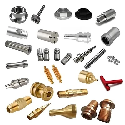

Many hardware product managers and electronics procurement professionals face the same costly mistake: over-specifying tolerances on drawings for CNC machining tolerances electronic components. This often results in 2–5x higher quotes, extended lead times, and unnecessary manufacturing complexity without any meaningful improvement in product performance. In fast-moving markets like 5G infrastructure, consumer electronics, EVs, and medical devices, understanding "what precision you actually need" can make or break project margins and delivery schedules.
Tight tolerance CNC machining electronics projects frequently suffer from this imbalance. For instance, a simple connector housing that only needs ±0.05 mm might be labeled ±0.005 mm across the board, dramatically inflating costs. Conversely, insufficient precision on critical mating interfaces leads to assembly failures, EMI leakage, or costly field returns.
What Is CNC Machining Tolerance and Why It Matters for Electronic Parts
Dimensional tolerance defines the acceptable variation range for a part's features. It appears on drawings as ± values (e.g., 10.00 ± 0.05 mm) or, more effectively, through Geometric Dimensioning and Tolerancing (GD&T) per ASME Y14.5, controlling flatness, perpendicularity, position, and profile.
In CNC machining tolerances electronic components, tolerances directly impact:
Reliable mating in connectors and sockets
EMI shielding effectiveness through proper cavity sealing and contact pressure
Thermal performance in multi-material assemblies
High-frequency signal integrity, where minor variations can affect impedance
International Tolerance (IT) grades serve as useful benchmarks: IT7–IT9 cover most general electronic parts, while IT5–IT6 are reserved for precision fits.
In our experience supporting electronics procurement, unclear or overly tight tolerances cause 30–40% of quoting delays and unexpected cost overruns. Early DFM review helps align design intent with actual manufacturing capability.
Standard Tolerances vs Tight Tolerances: Cost and Lead Time Impact
Standard tolerances (±0.1 mm to ±0.05 mm) deliver excellent results for the majority of features in electronics. They support standard machining parameters, faster cycle times, and reliable process capability (CpK ≥ 1.33).
Tight tolerances (±0.01 mm or ±0.005 mm) - typical in tight tolerance CNC machining electronics - demand slower feeds, multiple finishing passes, climate-controlled shops, premium tooling, and intensive inspection. This commonly increases costs by 2–6x and extends lead times from 5–7 days to 2–4 weeks or more.
Key procurement principle: Apply tight tolerances only where they are functionally required. For example, a PCB bracket mounting hole can safely use ±0.1 mm, while a high-speed RF connector pin may need ±0.01 mm for consistent contact resistance.
One anonymous client in the 5G sector reduced their prototype costs by 38% simply by moving from blanket ±0.01 mm to a smart tolerance hierarchy. In practice, 60–75% of dimensions on typical electronic drawings can use standard tolerances without compromising performance.
ISO 2768 Tolerance Standard
Most professional CNC suppliers default to the ISO 2768 CNC machining tolerance standard when specific tolerances are not called out on drawings. This practical standard includes several classes:
ISO 2768-m (medium): The most common choice for electronics - ±0.1 mm for linear dimensions up to 30 mm, with graduated values for larger sizes.
ISO 2768-f (fine): Tighter requirements for precision parts.
ISO 2768-c (coarse): For non-critical features.
Critical procurement notes:
ISO 2768 only applies to untoleranced dimensions.
Always combine it with GD&T for functional critical features.
Clearly specify the class (e.g., ISO 2768-mK) in the title block.
Confirm your supplier's actual process capability during DFM - many exceed the standard on key features.
Relying on ISO 2768 appropriately prevents ambiguity and helps control CNC machining tolerances electronic components costs. Overriding it with custom tight tolerances everywhere is one of the quickest ways to inflate budgets.
Tolerance Requirements by Application: Connectors, Enclosures, Heat Sinks, and PCB Brackets
Tolerance strategy must match the component's real functional needs. Here is a practical procurement reference table:
|
Component Type |
Recommended Tolerances |
Key Risks if Wrong |
Typical Surface Finish (Ra) |
Cost Impact |
|
Connectors |
±0.01 – ±0.005 mm (critical contacts) |
Poor signal integrity, EMI leakage |
0.4 – 0.8 µm |
High |
|
Enclosures |
±0.05 – ±0.1 mm |
Fit issues, aesthetics |
1.6 – 3.2 µm |
Medium |
|
Heat Sinks |
±0.05 mm (base flatness), ±0.1 mm (fins) |
Thermal resistance increase |
0.8 – 1.6 µm |
Medium-High |
|
PCB Brackets |
±0.1 mm |
Mounting misalignment |
3.2 µm |
Low |
CNC precision electronic parts tolerance works best with a clear hierarchy: tightly tolerance only critical features (usually <25% of dimensions) and let ISO 2768 handle the rest. This approach balances performance and cost effectively.
How Tight Tolerances Affect Surface Finish and Material Choice
Tighter tolerances are closely linked to surface finish requirements and material selection - factors that significantly influence procurement costs.
Achieving ±0.005 mm usually requires surface finish CNC electronic quality of Ra 0.8 µm or better, which demands finer tools, slower parameters, and sometimes additional polishing or honing steps. For anodizing tight tolerance parts, you must account for coating thickness (typically 8–25 µm), which affects final dimensions and requires leaving extra stock.
Procurement implications:
Aluminum is easier and cheaper to machine to tight tolerances than stainless steel or titanium.
Plastics like PEEK need annealing and careful fixturing to maintain stability, increasing setup costs.
Overly tight tolerances on large flat surfaces (e.g., heat sink bases) can drive up costs dramatically due to flatness control challenges.
In one recent medical device project, relaxing non-critical surface finish requirements while keeping critical tolerances tight reduced unit cost by 27% without affecting performance. Understanding these trade-offs helps procurement teams make smarter material and tolerance decisions.
5 Ways to Reduce CNC Machining Cost Without Compromising Precision
Here are the most effective strategies we recommend to electronics procurement teams:
Implement tolerance hierarchy - Reserve tight tolerances for <20–25% of features only.
Default to ISO 2768-m - Avoid custom tolerances on non-critical dimensions.
Request early DFM review - Experienced suppliers often identify savings of 15–45% through minor design tweaks.
Optimize for machining setups - Group features that can be machined in one fixturing to reduce setup time.
Balance material choice with tolerance needs - Select alloys with better inherent machinability for precision areas.
Applying these approaches to how to reduce CNC machining cost with tolerances can deliver substantial savings in CNC machining tolerances electronic components projects while preserving required quality and reliability.
Three core principles for successful CNC machining tolerances electronic components procurement are:
Apply precision only where it functionally matters.
Leverage standards like ISO 2768 and GD&T intelligently.
Collaborate early with suppliers through structured DFM reviews.
By moving away from blanket tight tolerances and focusing on real requirements, you can achieve reliable CNC precision electronic parts tolerance at competitive cost and lead time.
Ready to optimize your next project? Upload your drawing here for a free DFM review and tolerance consultation. Our experienced team will help you balance precision, cost, and performance for your electronic components.
FAQ
Q: When do I actually need tight tolerance CNC machining electronics?
A: Only for critical mating surfaces, high-frequency contacts, or precision alignment. Most features work well with standard tolerances.
Q: How much can smart tolerancing reduce costs?
A: 20–50% is common when shifting from over-toleranced drawings to a proper hierarchy.
Q: What is the difference between ISO 2768 and GD&T?
A: ISO 2768 provides general defaults; GD&T offers precise functional control for critical features.