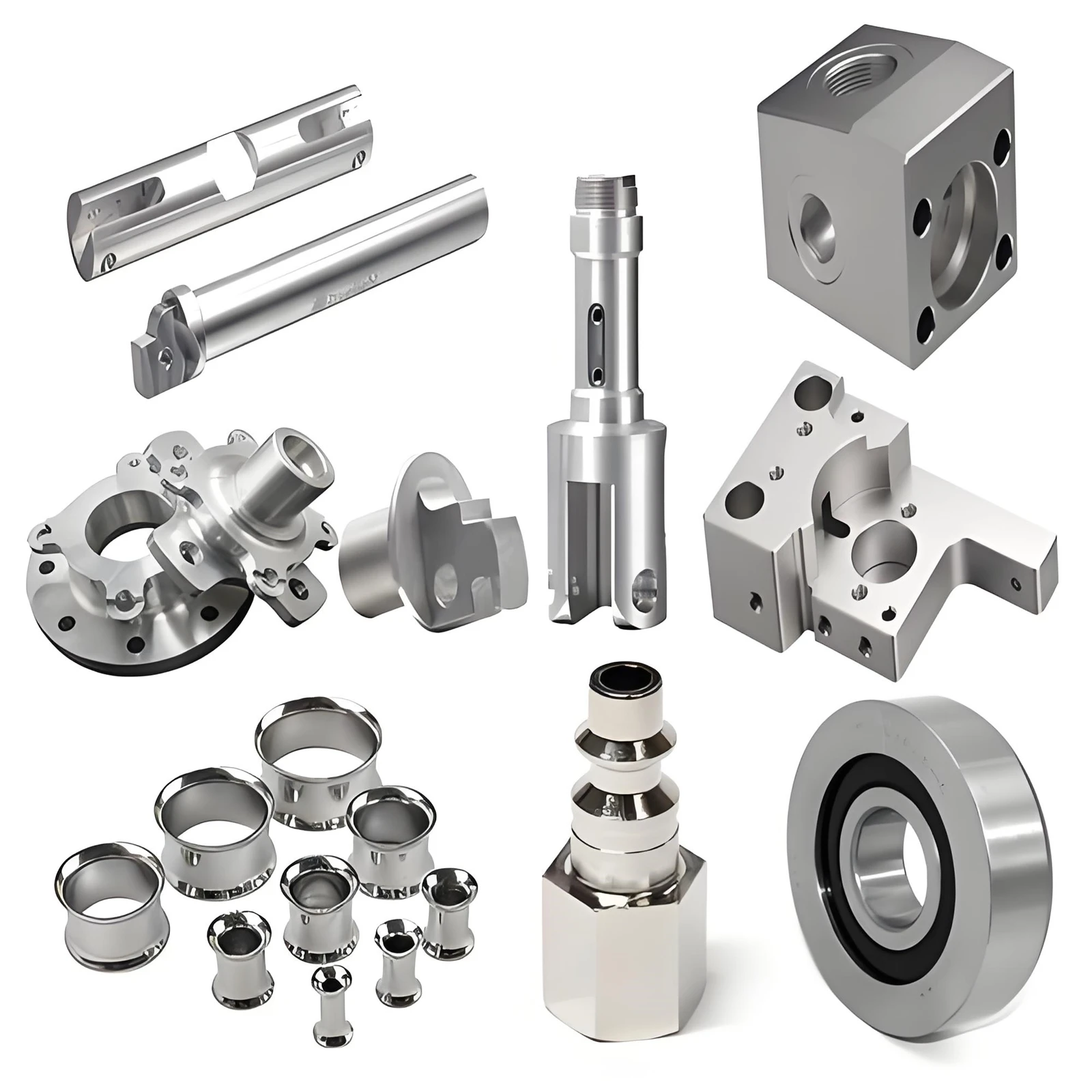

An aluminum bracket for an aircraft can look surprisingly similar to one used in an electric vehicle or an industrial robot. The material may be the same, and both parts may require milling, drilling, and finishing. Their manufacturing risks are still quite different.
The aircraft bracket may need to remain stable after most of the original stock has been removed. A vehicle component could spend years exposed to vibration, heat, lubricants, and road moisture. In medical equipment, a small burr or poorly controlled surface may interfere with assembly or cleaning. On a robotic arm, a slight error between a bearing seat and a motor mount can reduce positioning accuracy at the end effector.
Industrial CNC machining therefore begins with the part's function, not the machine selected to produce it. A useful manufacturing review considers where the component will be installed, how it will be loaded, which dimensions control assembly, and what happens if those dimensions drift. The answers shape material selection, workholding, machining sequence, inspection, and finishing.
The Application Changes the Machining Plan
Weight reduction is a recurring concern in aerospace manufacturing. Brackets, avionics housings, structural connectors, and other machined components often contain deep pockets and thin walls because excess material has been removed from areas that do not carry the primary load. This approach improves the strength-to-weight ratio, but it can also make the part more sensitive to residual material stress, clamping pressure, and cutting heat.
For cnc machining aerospace parts, a drawing review should identify thin sections, difficult tool access, and critical relationships between mounting surfaces before material reaches the machine. A 7075 aluminum bracket, for example, may appear straightforward in the CAD model. Once a large percentage of the stock is removed, the remaining structure can move. Roughing and finishing the entire part in one uninterrupted operation may leave dimensions that look correct in the fixture but change after unclamping.
Leaving a controlled finishing allowance or separating roughing from final machining can improve stability. Some geometries also benefit from a different stock form or workholding method. There is no single sequence for all cnc machining aerospace parts because wall thickness, material condition, datum selection, and tolerance relationships change from one drawing to the next.
Automotive work is often driven by the stage of the program. During development, engineers need physical parts for assembly checks, thermal testing, sealing tests, and road trials. A hole position or mounting feature may change after the first vehicle build. CNC machining allows those revisions to be introduced without waiting for new production tooling.
The priorities shift after the design is released. Repeat orders for cnc automotive parts need stable fixtures, known tool life, and inspection points that can be used from one batch to the next. Transmission components, battery system parts, suspension connectors, sensor housings, and aftermarket hardware may all face vibration and temperature changes, but their material and surface requirements are not interchangeable.
Aluminum works well for many lightweight housings and brackets. Loaded shafts or connectors may require carbon steel, alloy steel, or stainless steel. Engineering plastics can be practical for guides, bushings, and electrical insulation. The correct choice depends on the environment around the part as much as on machinability. When quoting cnc automotive parts, the supplier needs to know whether the component is a short-lived test article, a functional prototype, or a part intended for recurring production.
Medical and robotics projects place more emphasis on small features and positional relationships. medical cnc machining may involve instrument components, diagnostic equipment, laboratory systems, rehabilitation devices, or parts used in drug-delivery equipment. Narrow slots, fine threads, small holes, and thin sections are common. These features can be machined successfully, but tool deflection, heat, burr control, and inspection access need to be considered early.
A material description such as "stainless steel" or "medical plastic" is too broad for a production quotation. The drawing should identify the grade and any required condition. Whether the part will be sterilized, exposed to chemicals, subjected to wear, or used only as a structural element will affect the decision. Finishing requirements matter as well. Passivation, polishing, anodizing, and other treatments can alter surface condition or final dimensions, so they should be planned together with machining.
Inspection for medical cnc machining must reflect the feature being controlled. A machine may be capable of producing a small hole or narrow slot, yet ordinary hand tools may not provide a reliable measurement. Critical locations, datum relationships, and geometric tolerances may require optical or coordinate-based inspection. The drawing and inspection plan need to tell the same story.
Position is equally important in robotics cnc machining. A joint housing can pass its individual diameter checks and still cause assembly trouble if its bearing seats are not aligned with the motor mount. Small errors may show up later as backlash, vibration, uneven wear, or lost repeatability.
Robot arms, grippers, sensor mounts, shafts, and transmission components also balance different material needs. Aluminum reduces moving mass. Steel provides strength and wear resistance where loads are higher. POM, nylon, PEEK, and PTFE can serve as guides, insulators, or low-friction components. During development, quantities may be small and revisions frequent. When the design settles, robotics cnc machining requires fixtures and inspection routines that preserve the same functional relationships across later batches.
Machine Selection, Tolerances, and Cost
A part does not need five-axis machining simply because it belongs to a demanding industry. Plates, regular housings, and brackets with features accessible from one direction can often be produced efficiently on a three-axis machining center. Four-axis or five-axis equipment becomes useful when the cutter must reach several faces, angled holes, deep cavities, or continuous contours.
Setup count deserves close attention. Repositioning a part takes time and can introduce another source of alignment error. Multi-axis machining may allow several critical features to be completed without unclamping the workpiece. On the other hand, a well-designed fixture can sometimes make two straightforward setups more economical than a complex multi-axis program. The best choice depends on tool access, quantity, tolerance relationships, and total production time.
The same functional approach should guide tolerance decisions. Bearing locations, sealing surfaces, locating holes, and motion-related fits may need close control. An exterior edge or noncritical cover dimension usually does not require the same precision. Applying unusually tight tolerances across the entire drawing increases machining and inspection time while giving the finished assembly little or no practical benefit.
Clear datums are more useful than a page filled with narrow plus-or-minus limits. They tell the machine shop how critical features relate to one another and provide a consistent reference for inspection. This is especially important when several faces are machined in different orientations.
Surface finish also needs a purpose. Sealing faces, sliding surfaces, and fatigue-sensitive areas may require specific roughness values. A hidden mounting surface may only need a standard machined finish. If the component will be anodized, plated, polished, passivated, or painted, coating thickness and edge condition should be considered before final dimensions are assigned.
Part size alone says little about cost. A small stainless steel component with deep pockets and precision holes may require longer cycle times and more expensive tooling than a large, simple aluminum plate. Stock size, removal volume, material behavior, setup time, inspection, and finishing all contribute to the quotation.
Order quantity changes the cost structure too. Programming and setup are absorbed by one unit in a prototype order but spread across the batch in repeat production. At higher quantities, fixture design and tool-life control become more important. A slightly higher setup cost may reduce cycle time and variation enough to lower the overall production cost.
From a Useful RFQ to Repeat Production
A screenshot and a few overall dimensions are rarely enough for an accurate quotation. The 3D CAD model defines the geometry, while the 2D drawing communicates material grade, datums, critical tolerances, threads, surface roughness, and finishing requirements. Quantity, inspection documents, and the target schedule should be included from the beginning.
When a material, tolerance, or finish can be changed, the acceptable range should be stated. This allows the manufacturing team to suggest a more stable process without guessing which requirements are flexible. A slightly larger internal radius, for instance, may allow the use of a shorter and more rigid cutting tool. Relaxing a nonfunctional tolerance can reduce inspection time without affecting assembly.
The first prototype is also an opportunity to improve the drawing. It may reveal that a deep hole serves no functional purpose, a wall is too thin for stable machining, or a specified finish is unnecessary on a hidden surface. Addressing these issues before repeat production is often more valuable than negotiating a small reduction in the prototype price.
Youde reviews projects using the customer's CAD files, engineering drawings, material requirements, quantities, and finishing specifications. Depending on the part, the machining plan may involve CNC milling, CNC turning, or multi-axis machining. Projects can start with a prototype or validation batch and move into recurring production after the design and process have been confirmed. Tolerance, lead time, and machine selection are evaluated against the actual drawing rather than treated as universal figures.
A useful supplier comparison starts with the drawing review. If a shop can identify unstable walls, inaccessible features, conflicting tolerances, or inspection difficulties before quoting, it is more likely to prevent problems during production. The proposed first-piece and inspection plan then shows whether the supplier is prepared for repeat orders or only focused on completing the initial batch.
Price belongs in the decision, but it should be compared alongside manufacturing risk. A lower quotation offers little savings if unclear requirements later cause rework, rejected parts, or assembly delays. Giving the supplier complete technical information makes the comparison more meaningful and provides a stronger foundation for moving from prototype to stable production.
Tags: cnc machining aerospace parts, cnc automotive parts, medical cnc machining, robotics cnc machining